#
YL620 Variable Frequency Drive (VFD) by Yalang
Variable Frequency Drive (VFD) devices have several different names. To name few; Frequency Converter, Adjustable Speed Drive, and Frequency Inverter. Some of these names are better describing the product and others are ambiguous and therefore confusing. The YL620-A by Yalang will be referred here as VFD.
This document shares guidelines and tips that are either not available or not clear in the official English user's manual (YL620-A-Inverter-Manual.pdf).
#
Table of Content (TOC)
Setting Parameters Restore Factory Defaults Controlling a Single Phase Motor Jog Mode Displaying RPM Calculating the RPM/Frequency Ratio Calculating Torque Using a Stroboscope to Measure RPM Braking Resistor Detachable Control Panel Open Questions
#
Setting Parameters
To set a new value to a parameter follow the next steps:
- Press the
STOPkey to make sure the motor is stopped. The internal fan will work for a short time. This allows the user to verify that the fan is functioning. - Press the 'PRGM' key to enter the programming mode.
- Select the program group number (the first two digits after the
P). Do that using theDISP(to scroll horizontally among the displayed digits) andUPandDOWNarrow keys to set the requested program group number. - Select the parameter number for the selected group (the last two digits after the
P). Do that as described in the previous step. - Press the
SETkey to enter the setting mode for the selected program group and parameter. - The current value is displayed flashing.
- Change the value using the
DISP(to scroll horizontally among the displayed digits) and 'UP' and 'DOWN' arrow keys to set the requested value. - Press the
SETkey again to store the parameter in a temporary buffer (i.e., Inverter Host/Panel). - The Inverter remains in the programming mode, flashes
-End-shortly, and advances to the next parameter. - Repeat the above steps 5 to 9 to modify additional parameters.
- When done, Press the
PRGMkey again to leave the programming mode. - To commit the changes and transfer (i.e., Upload) all the parameters from the temporary buffer (i.e., Inverter Host/Panel) to the Inverter Controller (i.e., permanently stored) you can do one of two things:
- Option 1: Restart the Inverter (i.e., disconnect from power) and wait few seconds for the transfer to complete, during which
Err 10(i.e., 'Power Disconnected' message) will be displayed. After completing the transfer, the Inverter will turn off. - Option 2: Press the 'STOP' key, keep it pressed, and then press the 'UP' arrow key. The display will scroll through all the parameters and finally will display
u 1500(i.e.,ufor upload and1500for the last parameter scanned), and lock all keys, except for thePRGMkey. To return to normal mode press thePRGMkey. You can now continue using the Inverter as usual, however, the new parameters will become effective only AFTER a complete restart cycle (i.e., see Option 1 above). TBD: This last statement needs to be verified, as I have seen some parameters becoming active after using Option 2, WITHOUT the need for a complete restart cycle.
Note: If instead of committing the recent changes you would like to rollback to the current permanent parameters stored in the Inverter Controller:
- Exist the programming mode if the Inverter is still in this mode.
- Press the
STOPkey, keep it pressed, and then press theDOWNarrow key. The display will scroll through all the parameters and finally will displayd 1500(i.e.,dfor upload and1500for the last parameter scanned), and lock all keys, except for thePRGMkey. To return to normal mode press thePRGMkey. You can now continue using the Inverter as usual.
#
Restore Factory Defaults
The Inverter may not have the default factory setting being active out of the box. It is suggested to start with restoring the factory defaults before setting any parameter.
To restore the factory defaults, set the following parameter (see the above
P00.13 = 10
Notes:
- When this value is set for restoring the factory defaults, the Inverter will not allow any other parameters setting.
- For this 'Restore Factory Default' action to take effect, the Inverter has to be restarted (i.e., see Option 1 above).
- Not all the parameters will be restored to factory settings. The user's manual refer to that as "electrical parameter not included...". TBD: The list of the protected custom parameters needs to be verified.
#
Controlling a Single Phase Motor
The YL620 VFD (200VAC, 50Hz) is intended for use with a single phase input (Main Power) and three phase motor. The user's manual does not mention anything about supporting a single-phase motor.
However, it can be connected to a capacitor-run single-phase induction motor with appropriate ratings.
Let's start by a brief introduction to capacitor-run single-phase induction motors.
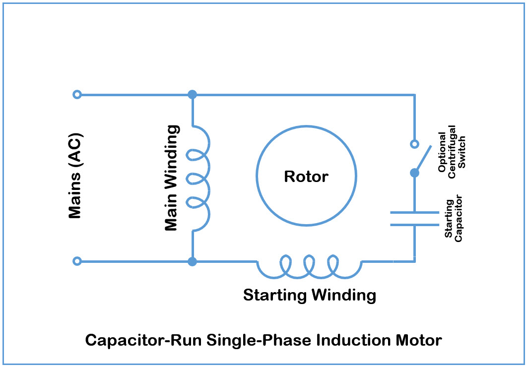
A capacitor-run single-phase induction motor has one capacitor, two windings (i.e., starting and main windings) mounted on the stator, and a cage winding placed on the rotor.
It may also have a centrifugal switch that disconnects the capacitor after the motor starts.
Following is a typical connection diagram of a capacitor-run single-phase induction motor:
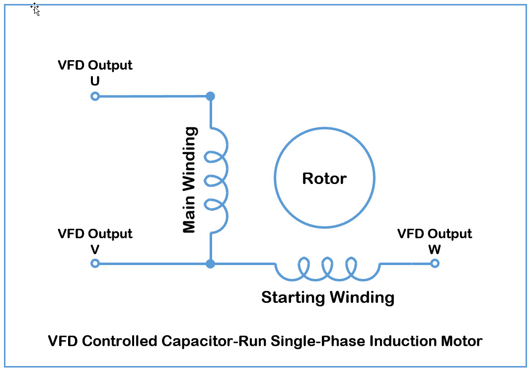
Now that we understand how typical capacitor-run single-phase induction motors are connected, we will make the connection changes required to control it using a VFD with 3-Phase output.
The following steps are needed in order to connect this type of motor to this VFD:
- Remove the inner capacitor of the motor.
- Connect the two windings of the motor (
startingandmainwindings) to the U, V, and W outputs of the VFD as follows:
#
Jog Mode
The motor can be operated in a jog mode (aka, 'inching'), which allows to manually rotate the motor 'inch by inch'.
To issue a jog command press the STOP key, keep it pressed, and then press the DISP key. The number of revolutions depends on the duration of the press. A brief jog can be less than one revolution. There is no upper limit to the number of revolutions (unless you have some sort of external range limit).
The direction of the jog is defined by the F/R key.
There are several configuration parameters that define the jog motion:
- P06.17 Jog Acceleration Time (Range = 0.1-6553.5, Default = 2.0) TBD: Units?
- P06.18 Jog Deceleration Time (Range = 0.1-6553.5, Default = 2.0) TBD: Units?
- P07.16 Forward Jogging Frequency (Range = 0-120HZ(400Hz), Default = 15.0Hz)
- P07.17 Reverse Jogging Frequency (Range = 0-120HZ(400Hz), Default = 15.0Hz)
#
Displaying RPM
In order to display RPM, there are two parameters involved:
- P00.23 (Display Proportion Constant)
- P00.24 (Display Mode)
The first (P00.23) is mandatory and the second (P00.24) is optional, as described in the following sections.
#
Setting the 'Display Proportion Constant'
In order to display RPM, the ratio between the actual RPM and the Frequency, as provided by the VFD to the motor, at the point of interest (i.e., on the motor shaft or on the end spindle after a gear) needs to be known. This can be done by calculation (approximated by ignoring 'slip') or one-time measurement with an external device (accurate).
See
The RPM Strob iOS App served me successfully to measure the actual RPM of my motor for several frequencies. See
Once we have the RPM/Frequency ratio, we can set it as percentage [%] in P00.23 (Display Proportion Constant).
If you have a gear and want to display the RPM of the final RPM of the spindle after the gear, then you need to multiple the RPM/Frequency ratio with the gear ratio and use the result to set P00.23 (Display Proportion Constant).
#
Displaying the 'User Variable' as RPM
At any time you can scroll through the display modes in a cyclic manner by pressing the SET key. This is regardless of the value of P00.24 (Display Mode). There are 13 display modes, each showing different data. These modes correspond to the possible modes for P00.24 (i.e.,values 0-12). The order of the scroll matches the order of the modes values cyclically.
After setting P00.23 (Display Proportion Constant) we can display the RPM by scrolling the display, as described above, until we reach the "user variable" (indicated by lower case 'u' on the left digit). The displayed "user variable" is the result of multiplying the value in P00.23 (Display Proportion Constant) with the current Frequency provided to the motor, and this reflects the RPM at the point of interest (i.e., on the motor shaft or on the end spindle after a gear).
To set the "user variable" as the default display mode that will be shown when the VFD is turned on, set P00.24 (Display Mode) with the value 9.
Note that also with P00.24 = 9 (display user variable), you can still scroll through the various display modes in a cyclic manner, as described above.
#
Numerical Examples
The following examples were done with a YL620 VFD (200VAC, 50Hz) connected to a small (200VAC, 50Hz, 0.17A) capacitor-run single-phase induction motor. See
The basic parameters for the following examples are:
- P00.04 Max Frequency = 50 Hz
- P03.08 Panel Potentiometer Lower Frequency Limit = 20 Hz
- P03.08 Panel Potentiometer Upper Frequency Limit = 50 Hz
- P12.20 SVPWM model = 0 (the value of 1 for a single-phase motor, didn't work well)
#
Example 1
The above mentioned two parameters for displaying the RPM (also factoring the gear ratio) are:
- P00.24 Display Mode = 9 (display user variable)
- P00.23 Display Proportion Constant = 200% (Hz to RPM conversion ratio of 2)
In this case, when the motor runs the display will show the following messages depending on the speed set by the potentiometer:
For minimal speed: "u 400" For maximal speed: "u1000"
Please note that there is no decimal point in this example. I think this is a bug in the firmware installed on my VFD.
As a workaround I set the P00.23 to 20% instead of 200% and got:
For minimal speed: "u 40" For maximal speed: "u 100"
This refers to 40 RPM and 100 RPM, respectively. In this case they represent RPM which is 2 times the motor frequency.
#
Example 2
- P00.24 = 9 (display user variable)
- P00.23 = 40% (Hz to RPM conversion ratio of 4)
Note that due to the decimal point presumably bug, P00.23 is set to 40% instead of 400%.
The displayed range now for the new scaling value is:
For minimal speed: "u 80" For maximal speed: "u 200"
This is exactly what I was looking for.
#
Calculating the RPM/Frequency Ratio
The approximated ratio between RPM and motor Frequency, while ignoring 'slip' is:
RPM [rev/min] = (120 x Frequency)/(#poles)
Notes:
- The RPM formula is based on the fact that the synchronous speed for an electric induction motor is determined by the power supply frequency, and the number of poles in the motor winding. It rotates inversely proportional to half number of poles per one mains cycle. The factor of 60 is only for converting minutes to seconds.
- A variable frequency drive (VFD) modulates the speed of an electrical motor by changing the frequency of the power supply.
- Based on The Engineering Toolbox, an induction motor will never reach its synchronous speed. If it did - the rotor would appear to be stationary to the rotating stator field since it would rotate with the same speed. With no relative motion between stator and rotor field no voltage will be induced in the motor. The speed of an induction motor is therefore limited to a speed below synchronous speed and the difference between synchronous speed and actual speed is called slip.
- Since induction motors slip the full-load, RPM will be somewhat less than the calculated speed. As an example, a motor rating plate stating 1,425 RPM at 50 Hz, which is just below 1,500 RPM, must be a four-pole motor.
- The number of poles for the motor (i.e., #poles) is known by using the above formula with two numbers taken from the motor nameplate (Base Frequency and nominal RPM for the Base Frequency).
#
Example
For instance, if the nameplate specifies Base Frequency of 50 Hz and 1,425 RPM then,
Approximated #poles = (120 x Frequency)/RPM = (120 x 50)/1,425 = 4.21
However, the number 1,425 RPM is with 'slip'. To find the synchronous RPM that corresponds to the Base Frequency, we need to find the nearest feasible value that gives an integer number of poles in the above formula. In this case, the synchronous RPM is 1,500 which gives #poles equals to 4.
The approximate ratio between RPM and Frequency is given then by:
RPM/Frequency = 120/(#poles) = 30
Now we know that for our example:
RPM = 30 x Frequency
#
Calculating Torque
Following is a simple equation for calculating Torque for given HP and RPM:
Torque [lb-ft] = (HP x 5252)/RPM --> Torque [N-m] = 1.356 x (HP x 5252)/RPM = Torque [N-m] = (HP x 7125)/RPM
Notes:
- The above Torque formula is using the common magic 5,252 number where horsepower and torque are mystically intertwined.
- The Wen Power-Torque Calculator is helpful for various motor related calculations.
#
Using a Stroboscope to Measure RPM
There are many free and paid stroboscope smart-phone applications on the app store. Some are relying only on the built-in flash, while others rely on external accessories, such as lights that are control via the audio jack of the phone. The RPM Strob iOS App that uses the phone flash, served me successfully to measure the actual RPM of my motor for several frequencies.
Prepare a clear marker that can spin by the motor. I used a small rectangular piece of cardboard with a single radial marker line and attached it to the motor shaft.
Using any kind of Stroboscope, start with a flash rate higher than the estimated RPM and adjust the flash rate down. At some point you will stop the motion with only a single image of the object in view (e.g., a reference line).
For a single reference line spinning by the motor at 1,500 RPM you can see:
As can be seen from the above table, the actual RPM is the one showing only one line and if you double that flash rate you will see two line. For instance, in the table above, 750 RPM is not the actual RPM, because when you double it you get 1,500 RPM for which you still get only 1 line. However, 1,500 RPM is the actual as it fulfill the two conditions.
For more details see this short article on Using a Stroboscope to Measure RPM.
#
Braking Resistor
The optional braking resistor consumes the regenerating energy of the motor and shorten the ramp-down time.
The braking resistor can be connected to the '+DB-' connectors of the Main Circuit Terminals.
#
Resistor Parameters
The following recommendations are based on the user's manual:
- For inverter model YL620-1.5KW-220V, use 100W 100Ω resistor. This will support a 1.5KW motor.
- In order to prevent the braking resistor from burning out, please add an electromagnetic contactor and connect a surge absorber to the coil when using it.
- The surge absorber absorbs the switching surge current from the electromagnetic contactor and control relays.
- Be sure to consider the safety and ignitability of the environment when installing a braking resistor.The distance to the inverter should be at least 100 mm.
#
Programming the VFD for DC Braking
Based on the user's manual:
- Program group and number: P00.03
- Possible Values:
- 0: Decelerating Stop (default)
- 1: Coasting Stop
- 2: DC Brake Stop
Set the P00.03 program group and number to the value of 2. For details on how to do that, see the
#
Experiments
As an experiment, the following steps on were performed on a Yalang YL620 (200VAC, 50Hz) VFD:
- Preparations:
- Disconnect the VFD from power
- Connect a small (0.17A) capacitor-run single-phase induction motor (220VAC, 50Hz). For details see
Controlling a Single Phase Motor - Put a flag marker (e.g., small tape) on the shaft of the motor to indicate its position
- Connect a common 60-100W 220V (~60Ω for 60W) incandescent light bulb directly to the '+DB-' connectors of the Main Circuit Terminals.
- Connect the VFD to power
- Check Stop Time before using the DC Barking mode:
- Check that the P00.03 is set to the default value of 0
- Press
RUNto start the motor and wait until the motor reaches its final speed - Press
STOPto stop the motor - Make a mental note of how long it took the motor to stop (repeat the
RUN/STOPcycle at different RPM)
- Check the Stop Time after using the DC Barking mode:
- Program the P00.03 to the value of 2
- Press
RUNto start the motor - Press
STOPto stop the motor - Watch the effect of the braking resistor (it should stop much faster with the braking resistor)
The YL620 VFD supports several configurations to control the behavior of the DC Braking (e.g., P01.09-P01.15, P04.04, ). However, in this experiment, their default values were used.
Note also that the over current error message ER02 has a dedicated value of 7 indicating: "DC braking is too high. Decrease DC braking".
#
Detachable Control Panel
The Detachable Control Panel of the YL620 is connected using 4-wires, uncrossed flat cable (15 cm long). The cable is connected on each end to a PCB mounted JST-XH Top Entry type pin header (2.5 mm pitch).
The 4-wires are:
- GND
- A (Digital Level)
- B (Digital Level)
- VCC (5V)
The A and B wires are the UART Tx/Rx of the MODBUS protocol using 8 control bits, 1 stop bit, no parity. This was discovered by using a Logic Analyzer (i.e., Open Bench Logic Sniffer board with PulsView software). However, it is unclear if it is a standard or modified MODBUS protocol.
#
Open Questions
The following open questions are in addition to those on the parameters excel sheet:
- CLOSED: How to switch the display of the VFD to show RPM? Asked also by agflex in this forum without a good answer.
Answered: Read he solution in the
Displaying RPM section above. Note that I have posted this answer as a reply to the question by agflex. - CLOSED: How to measure and display the actual RPM (on the motor and on the end spindle of the lathe)? Will P00.24 with value of 6, 8, or 10 help?
Answered: Read he solution in the
Displaying RPM section above. - CLOSED: How to factor the gear ratio of the lathe in the display? Is P00.23 related to that?
Answered: Read he solution in the
Displaying RPM section above. - OPEN: What is the difference between P00.04 and P00.05?
- OPEN: How to use the equations in the above
Calculating RPM and Torque section in order to set the min and max output frequencies (P00.09 and P00.04) and the min and max displayed frequencies (P03.08 and P03.09)? - OPEN: How to avoid the long shutdown process of the Inverter that includes the persisting of the parameters? Locking the parameters by P00.13 didn't help.
- OPEN: What impact has the value of the number of poles (P12.02) on the performance? I have modified the value of the number of poles (e.g., 2, 4, 8), when the LG AirCond Fan Motor was connected, and there was no visible impact on the running speed or the torque.
- OPEN: How to mount the VFD next to the lathe/mill while protecting it from harmful materials?
- CLOSED: Can the DC Braking Resistor be disconnected while the VFD is set to support DC Brake Mode? Answered: I have tried it with a small (200VAC, 50Hz, 0.17A) capacitor-run single-phase induction motor and I have not noticed any damage to the VFD.
- CLOSED: How many wires are used to connect the detachable panel to the VFD? There are four wires marked as VCC, B, A, and GND.
- CLOSED: What is the power level of the detachable panel? The VFD provides 5V-DC to the panel.
- OPEN: What is the protocol used to connect the detachable panel to the VFD?
- OPEN: Can multiple detachable panels be connected to the same VFD? Answered: Not in its simplest mode. The MODBUS is point-to-point communication.
- OPEN: What is the relation between Huanyang and Yalang, and what is the difference between their VFD products?